A Deep Dive Into Samsung’s TrustZone (Part 1)
Motivations
After a general introduction on the ARM TrustZone and a focus on Qualcomm’s implementation, this new series of articles will discuss and detail the implementation developed by Samsung and Trustonic.
These blog posts are a follow up to the conference Breaking Samsung’s ARM TrustZone that was given at BlackHat USA this summer. While an event such as this one is a great opportunity to present a subject we have been working on, many details have to be overlooked to fit the 50-minute format. This blog post, and the following ones, will explain all the details that were missing from the presentation as well as release the different tools mentioned in the talk and developed along the way.
This series will be split into the three following parts:
- Part 1: Detailed overview of Samsung’s TrustZone components
- Part 2: Tools development for reverse engineering and vulnerability research
- Part 3: Vulnerability exploitation to reach code execution in EL3 on a Samsung device
Introduction
With the widespread use of mobile devices and embedded systems, security concerns are a priority that vendors need to address. The traditional architecture of a device running an operating system alone is not enough. In this paradigm, a single vulnerability in the kernel could lead to the compromise of the entire system.
In response to these issues, vendors conceived new technologies and means to enhance the security of their devices. Among these technologies are Trusted Execution Environments, or TEEs.
A Trusted Execution Environment is a secure zone in the CPU. It executes concurrently to the main operating system, in an isolated environment. It guarantees that the data and code executing inside the TEE maintain their integrity and confidentiality. This parallel trusted system is conceived to be more secure than the regular environment, called Rich Execution Environment, or REE, by using both hardware and software components to protect code and data alike.
This article series focuses on the TEE implemented by Samsung using the ARM TrustZone, most notably in their older Galaxy devices (S6 to S9). After introducing the different concepts inherent to the TrustZone technology in a first part, this article will provide an explanation on the components and inner workings of the Samsung’s TrustZone. A following article will be dedicated to the presentation of the different tools developed to ease the reverse engineering and exploitation processes. Finally, the third article will present different vulnerabilities affecting secure components in TrustZone and demonstrate how they can be exploited to get code execution in EL3, the highest privilege in the ARM architecture.
ARM TrustZone Technology
Embedded Security’s Current State
The traditional architecture of separating an operating system into userland and kernel space has seen many security improvements throughout the years. However, it does not seem to be enough. Developers have tried to make the attack surface on the kernel as little as possible, strengthening the verifications made on all user-controlled data, yet vulnerabilities can still be found and their exploitation able to compromise the entire system. From these observations, researchers and developers wondered how a system could be better protected, even if the kernel was corrupted at boot time or at runtime.
To address the issue of a kernel corruption at boot time, a possible solution would be the Secure Boot mechanism which prevents unauthorized code from executing during the bootloading process (e.g. bootloader stages, operating systems, etc.). A secure boot uses different stages to boot a system and each of them is responsible for loading, executing and verifying the cryptographic signature of the next one. However, using this process requires the first stage to be implicitly trusted. Usually, vendors write this first set of instructions directly into the System-on-Chip‘s (SoC) silicon, making it close to impossible to modify it. This first immutable and implicitly trusted stage is called a Bootrom.
Runtime corruptions can be mitigated using an hypervisor able to watch over multiple operating systems running concurrently, as shown in the following figure. Hypervisors can detect compromises and ensure the protection of the systems running under their supervision.
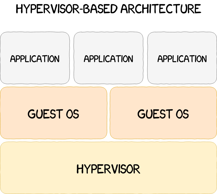
However, the hypervisor and the guest operating systems are all sharing the same physical memory. The separation between these environments is implemented only via software mechanisms. Under this paradigm, security issues such as virtual machine escapes, hypervisor corruption, etc. cannot be prevented. Taking these limitations into account, a possible enhancement of the system would be to isolate all the components at a hardware level, and thus were created Trusted Execution Environments, or TEEs. These secure and trusted environments use system-wide hardware isolation mechanisms to separate the resources of the CPU and the other peripherals. TrustZone, a TEE implemented by ARM, will be explained in detail in the following sections. In the meantime, an overview of the evolution of system-wide protections can be found in the figure below.

Existing TEEs
Several kinds of TEEs can be found on the market, but they can be divided into two categories given below.
- the TEEs used on desktop platforms, such as Intel SGX. As desktops are not the main subject of this article, these implementations will not be detailed.
- the TEEs used on mobile platforms, such as TrustZone, SEP, Titan M and others.
The last category can be subdivided in several implementation choices:
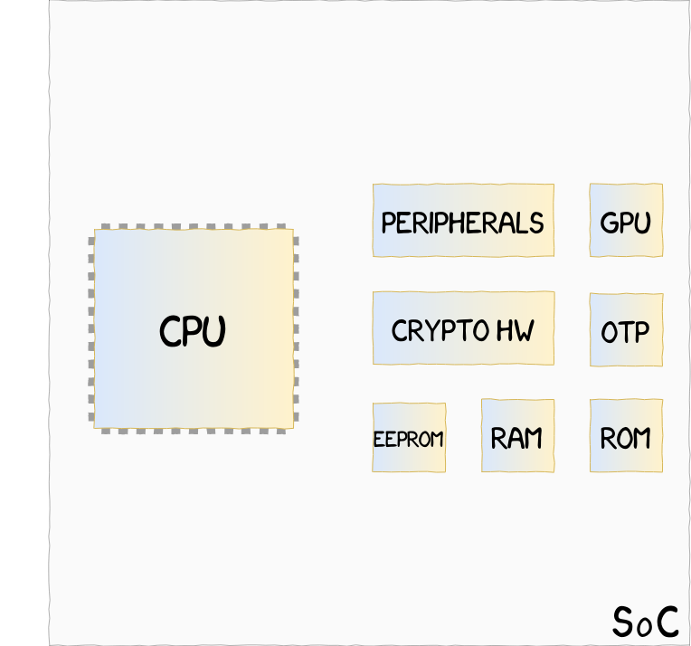
Virtual processor implementation, such as ARM TrustZone, where CPU and hardware resources are shared between a Secure and a Non-Secure state
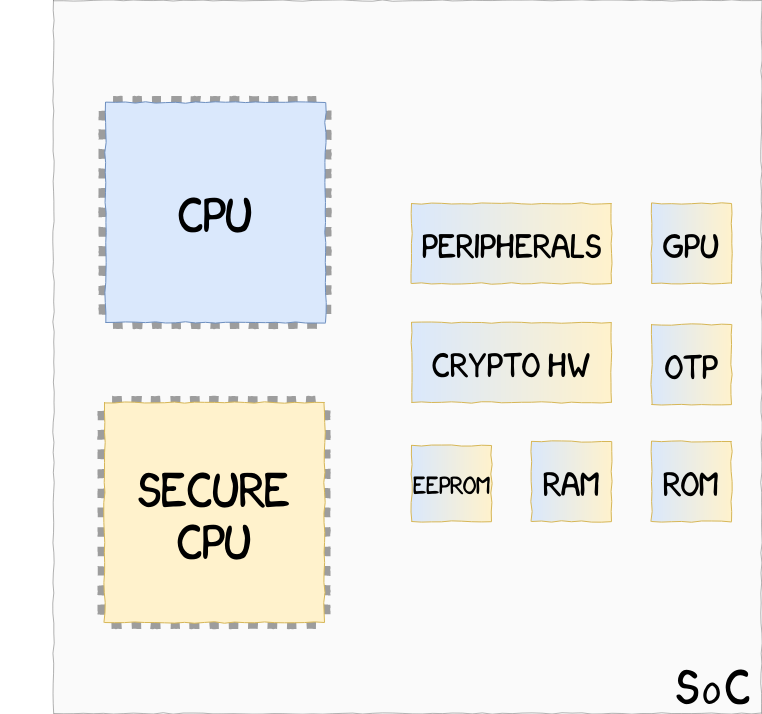
On-Soc processor implementation, such as Apple SEP, where two CPUs, one Secure and one Non-Secure, share hardware resources
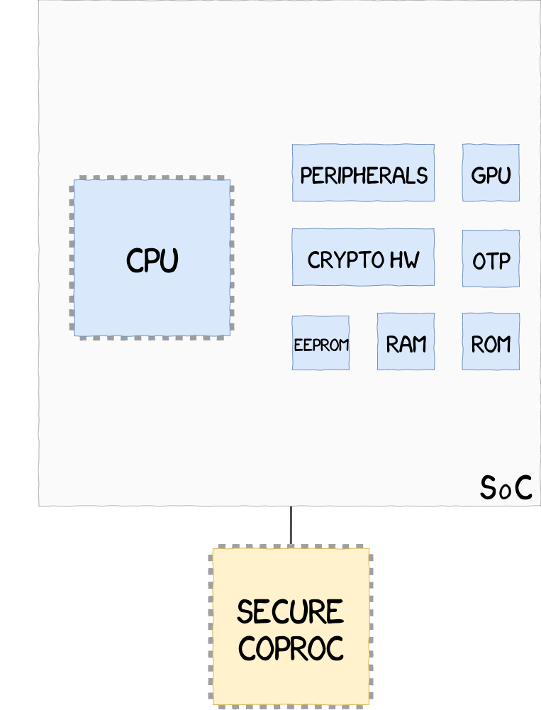
External Coprocessor implementation, such as Google Titan M, located outside of the SoC, and unable to access hardware resources within the SoC
This series of blog posts will focus solely on the ARM TrustZone technology.
ARM TrustZone Software Architecture
This section introduces the ARM TrustZone technology and details its different components and possible implementations. This article is not intended to provide an exhaustive presentation on ARM TrustZone. In the rest of this blog post, the details given will be mainly related to the ARMv8 flavor.
TrustZone is a system-wide hardware isolation achieved by separating the CPU into the Normal World and the Secure World. The Normal World contains and executes the main operating system, also called the Rich OS (e.g. Android, GNU/Linux, etc.), which the user primarily interacts with and which performs all the non-sensitive tasks. This operating system is distrusted by design, therefore all data communicated from the Normal World should be thoroughly checked before being used. In parallel exists the Secure World, which runs trusted code and stores/processes sensitive data.
In the following sections Normal World and Secure World will be abbreviated NWd and SWd respectively.
In order for the CPU to know whether it runs in secure or non-secure state, the ARM architecture uses the least significant bit of the Secure Configuration Register, or SCR, given in the following figure.

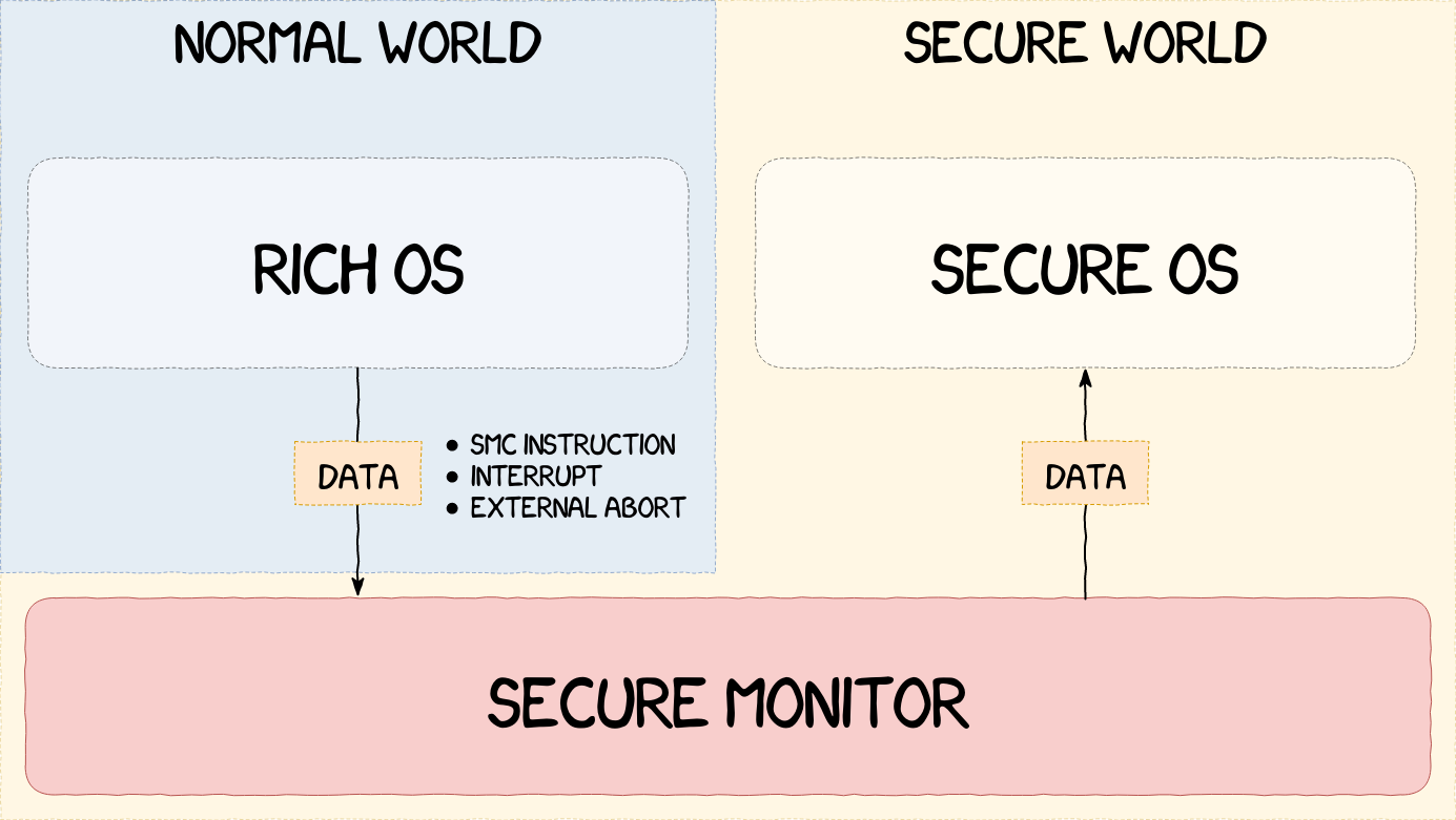
The separation being effective, the system now needs a secure mean of communication between the two worlds. To meet this requirement, ARM introduced the Monitor Mode, responsible for switching between the SWd and the NWd. It runs in secure state at the highest ARM execution level.
There are different ways to enter the Monitor Mode. From the NWd, it can be entered using a Secure Monitor Call, or SMC, instruction, through an interrupt or by raising an External Abort exception, as shown in the next figure. The same mechanisms can be used from the SWd in addition to writing directly to the Current Program Status Register, or CPSR, which can only be performed by privileged processes in the SWd.
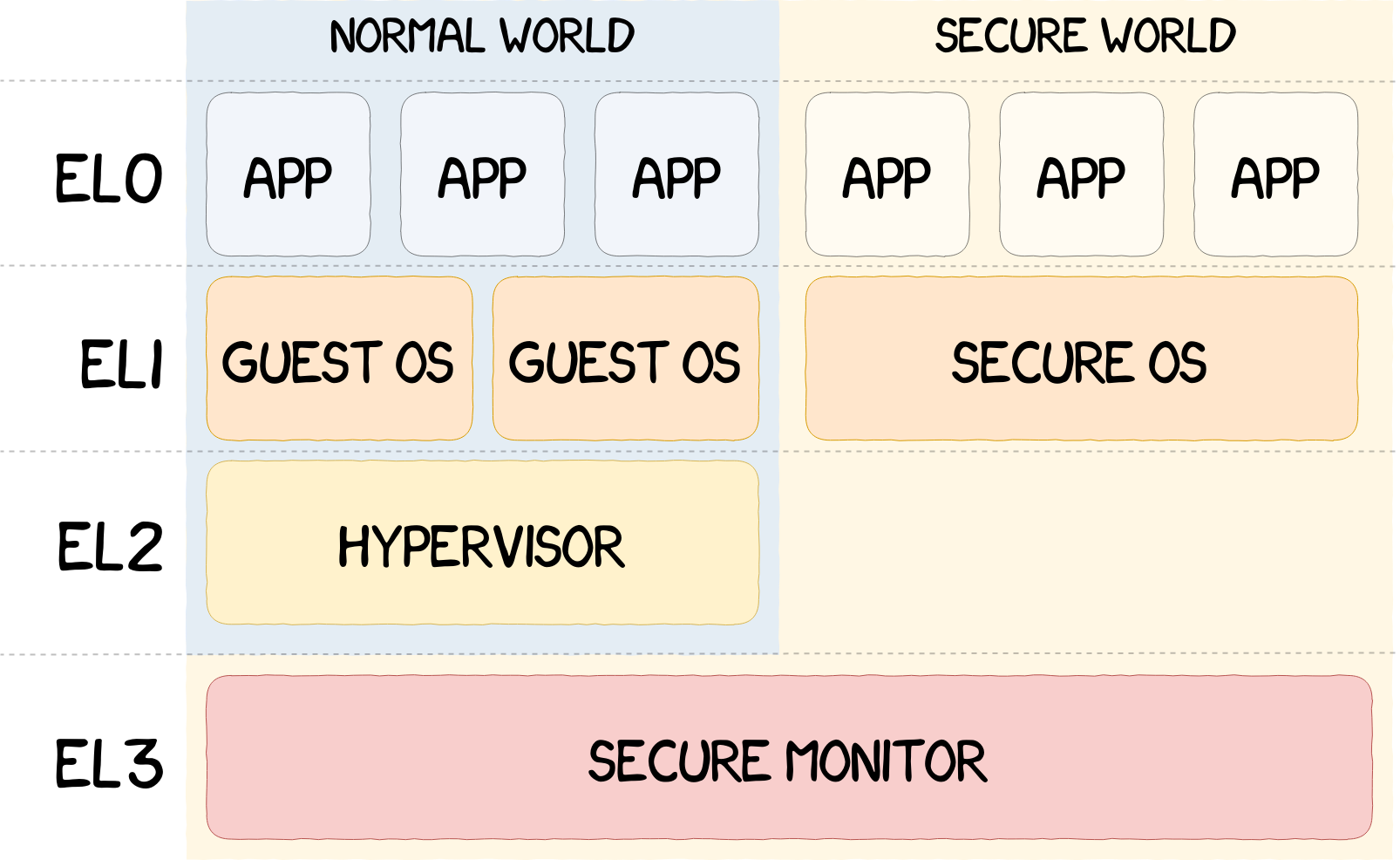
To get a better granularity in the permissions management, ARM uses different Exception Levels going from EL0 to EL3 (EL0 being the least privileged and EL3 the most). An overview of the use of these exception levels is given in the figure below.
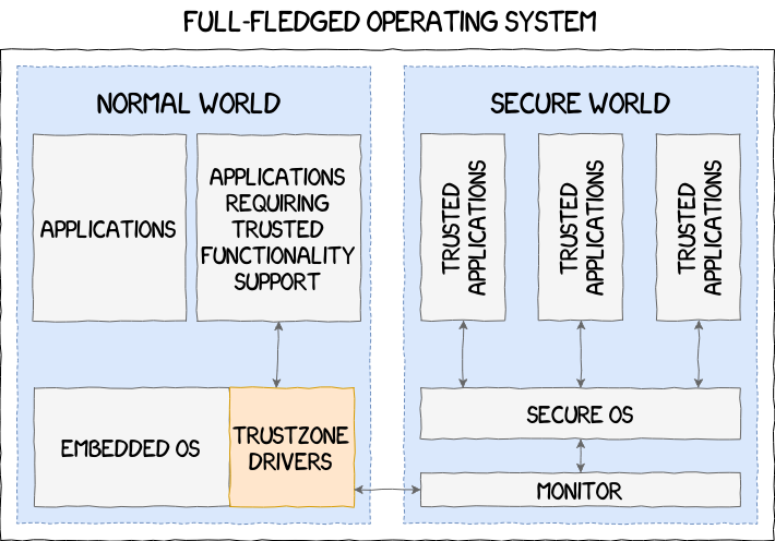
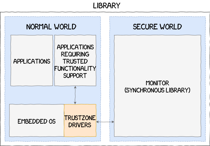
ARM provides all the necessary tools to vendors for them to build their own TrustZone implementation. There are few limitations and the SWd implementation can range from a simple library acting as an API, like in the Nintendo Switch, to a full-fledged operating system, such as the ones implemented by Samsung and Qualcomm, passing through intermediate solutions that we have never encountered yet:
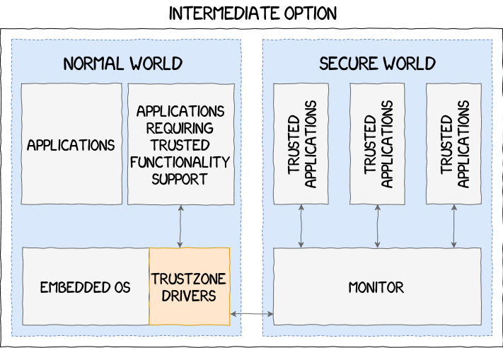
The following section focuses on the Samsung’s TrustZone implementation, its different components and their inner workings.
Samsung’s TrustZone Reverse Engineering
Samsung’s Implementation Overview
Samsung is one of the major OEM and, as such, tries to stay up-to-date with current technologies and provides as many features as possible to their customers. They have now used TrustZone in their devices for several years, starting with the Galaxy S3. On Exynos-based Galaxy devices, they started by using the implementation provided by Qualcomm before switching to their own (starting from the S6 for Galaxy models).
Generally, TrustZone is used to access hardware-backed features and to perform sensitive operations in a supervised manner (e.g. cryptographic engine, credentials storage, etc.). Samsung heavily uses TrustZone for Samsung Knox, a system-wide security toolbox developed by Samsung. Among the different components that constitute Knox, the Secure Storage API and the TrustZone-based Integrity Measurement Architecture, or TIMA for short, are two examples that rely on TrustZone to perform their operations. Knox also serves as a foundation to provide different services such as Samsung Pay, Samsung Pass, etc.
The current implementation, which is discussed in greater details in the sections Trustonic’s Trusted OS Kinibi and ARM Trusted Firmware (ATF) and Samsung’s Monitor, uses a modified version of the Arm Trusted Firmware, for the Secure Monitor, and a trusted operating system named Kinibi, which is developed by Trustonic.
Samsung uses the ATF project to implement their Secure Monitor and modified some part of it to make it fit their needs. They added their own runtime services which are used to supply custom SMC handlers without having to touch the current ones. For example, one of the added SMC handlers is responsible for registering Kinibi’s vector base address for SMCs handled by the Trusted OS.
As explained earlier, Kinibi, which this article series focuses on, is available on older devices (e.g. from the S6 to the S9 for Galaxy models). However, in more recent models such as the Galaxy S10, Samsung abandoned Kinibi for their own trusted OS called TEEGRIS. At the time of writing, and as far as we know, there are currently few resources available on the subject apart from a blog post by Alexander Tarasikov [TEEGRIS].
The following sections give more details on the TrustZone implementation based on Kinibi and the different components it is made of.
Trusted Applications
Trusted Applications, or trustlets, are the SWd counterpart to regular userland applications found in the NWd. As the trusted OS functionalities are limited, especially in the case of a micro-kernel, trusted applications can be used to extend them. It also provides a mean to lower the privileges needed by a process to perform a given task.
Trustlets are developed by trusted software vendors who need access to the TrustZone capabilities in order to enhance the security of their NWd applications. For example, streaming applications might need to use a DRM to protect digital content and this DRM could be implemented in a trusted application, like Widevine does, thus keeping the decryption keys from the NWd.
MCLF Format
The trustlets used in the Samsung’s Trustzone are executables using a proprietary file format called Mobicore Loadable Format, or MCLF. This format is pretty simple, which was useful to emulate trustlets as it will be discussed in the section dedicated to vulnerability research.
The MCLF header contains multiple information about the trustlet, including, but not limited to:
- its type;
- its UUID;
- its entrypoint;
- the addresses and sizes of its segments.
Every trustlet is comprised of three segments:
- the text segment that contains the trustlet’s code;
- the data that contains its initialised data;
- the bss segment that contains its uninitialised data.
After the MCLF header and segments data, the binary contains an embedded public key and a signature blob. When a trustlet is being loaded into the TEE, the hash of the public key is compared against an embedded hash within the TZOS binary, then the signature of the trustlet is verified. This mechanism prevents unauthorized developers from running their own code in TrustZone, only trusted vendors can get their trustlets to be signed by the OEM.

Note: to ease the reversing process of trusted applications, an IDA Pro loader for MCLF binaries written by Gassan Idriss can be used [IDA_LOADER]. A loader was also developed for GHIDRA and will be introduced in the second blog post.
Communicating With a Trustlet
Communications between the NWd and the SWd are performed using Software Interrupts (SWI) and World Shared Memory (WSM) buffers. SWI allows transferring the execution between the two worlds, while WSM buffers allow the transfer of data. In Trustonic’s terminology, these shared buffers are called TCI when communicating with a trustlet, and DCI when communicating with a secure driver, a special type of trusted applications with higher privileges detailed in the section Secure Drivers.
Trustlet Life-Cycle
Trusted applications have their own address space and are always loaded at virtual address 0x1000. Once they are running, they usually follow the same execution flow. They start by initializing different components, such as the stack, and then check the size of the TCI buffer sent from the NWd. Afterwards, the trustlet waits for commands in the TCI buffer using the McLib function tlApiWaitNotification, handles these commands accordingly and sends back the result to the NWd using tlApiNotify. This execution flow is illustrated in the figure below.
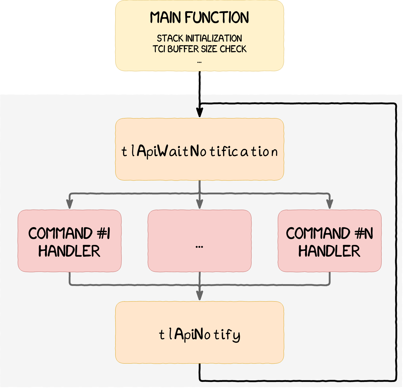
From an attacker point of view, the attack surface of the whole trustlet usually amounts to the one of the command handlers. These handlers mostly process user-provided data and must thoroughly check that every argument passed from the NWd respects the expected format. If an attacker were to obtain code execution in a trustlet, they would not be able to do much. However, they would be able to attack higher privileged processes, such as Kinibi itself or secure drivers, both of which are discussed in the following sections.
Secure Drivers
Secure drivers are a special flavor of trusted applications executing in the Secure World’s userland, but with higher privileges relatively to trustlets. These extra privileges boil down to the access to additional SVCs (Supervisor Calls), such as the ability to map specific physical memory ranges, using threads, or being able to make SMC, as detailed below.
Trustlets and secure drivers can communicate using IPCs and by marshalling the parameters sent. Secure drivers serve as interfaces for trustlets to access peripherals in a controlled manner. To access peripherals, secure drivers need to be able to map their physical memory, which is made possible using the functions drApiMapPhys, drApiUnmap, drApiVirt2Phys, etc.
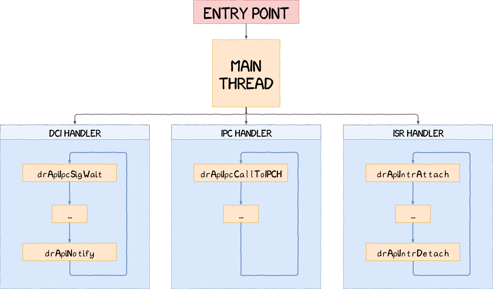
Another distinctive feature is the fact that drivers are multi-threaded applications. The common threads encountered are:
- a main thread acting as an exception handler;
- a DCI thread handling NWd messages;
- an IPC thread handling system/trustlets messages;
- an ISR thread handling interrupts.
Main Thread
This thread usually starts by initializing the hardware resources. It is also responsible for starting all the other threads described in this section. If one of the threads being run raises an exception, the main thread handles it and restarts the thread if needed.
DCI Thread
It is possible to communicate with a secure driver directly from the NWd. The system used is similar to the one implemented by trustlets and is based on a world-shared memory region called a DCI buffer. Commands and arguments are sent directly from the NWd in this buffer and a similar notification system based on drApiIpcSigWait and drApiNotify is used. Vulnerabilities in this handler could be exploited to get direct access to a secure driver from the NWd without passing through a trustlet.
IPC Thread
When reverse engineering a secure driver, the IPC handler is usually the interesting one. It can be identified by the call to drApiIpcCallToIPCH, the drApi function waiting for IPC messages. Arguments are passed into a single buffer to respect the data format required by the IPCs. When an IPC is received from a trustlet, the memory of the trustlet needs to be mapped into the address space of the secure driver, using the function drApiMapClientAndParams, so it can be accessed. Moreover, if pointers are sent as arguments, they need to be checked and translated to the address space of the driver to prevent out-of-band access. This operation can be performed by calling drApiAddrTranslateAndCheck.
ISR Thread
This thread simply attaches to an interrupt using drApiIntrAttach and waits for an interrupt to occur by calling drApiWaitForIntr. Detaching from an interrupt is done by calling drApiIntrDetach.
Trustonic’s Trusted OS Kinibi
Kinibi is a 32-bit micro-kernel developed by Trustonic and is implemented in Samsung’s TrustZone as its trusted OS. Even though Samsung Galaxy devices are based on a 64-bit architecture, Kinibi is able to run thanks to the ARMv8 AArch32 compatibility mode. This section details Kinibi’s architecture on devices ranging from the Samsung Galaxy S6 to the Galaxy S9. The foundation of this research is based on the Ekoparty talk and the series of blog posts, entitled Unbox Your Phone and released by Daniel Komaromy [UNBOX], presenting parts of Kinibi’s internals.
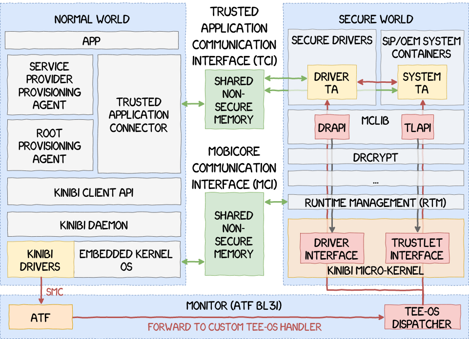
Since Kinibi is a micro-kernel, it is comprised of multiple components. These components are referenced in a table called image header and found in Kinibi’s binary, as shown in the following figure.
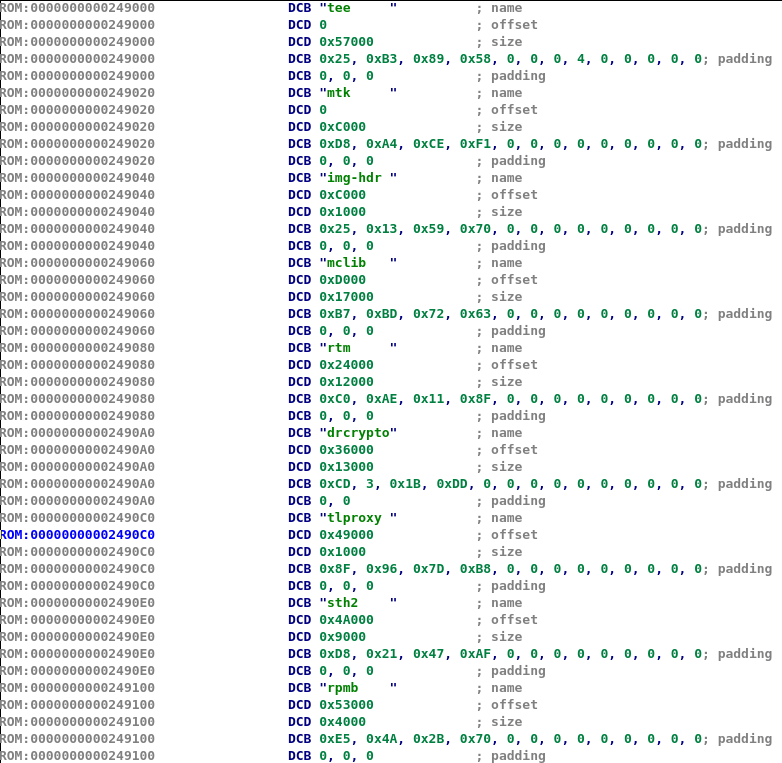
This table can be found in the binary by searching the marker “t-base” or “tee”. The first element of this table represents the TEE-OS itself while the others are the components inside the TEE-OS. Elements stored in this table can be represented using the structure given in the snippet below.
struct element {
  char name[8];
  int offset;
  int size;
  char padding[0x10];
}
Brief descriptions of these components are given in the list below.
- mtk: Micro T-base Kernel, the actual kernel, as its name suggests, responsible for performing privileged operations;
- img-hdr: the table describing Kinibi’s elements;
- mclib: the shared library implementing frequently used functions, similarly to the libc;
- rtm: the Run-Time Manager;
- drcrypt: the Crypto Driver;
- tlproxy: the Secure File System library for trustlets;
- sth2: the Secure File System for secure drivers;
- (Samsung S9) rpmb: this component is unknown at the moment.
The whole architecture is illustrated in the next figure.
Run-Time Manager
One of the most important and critical component is the Run-Time Manager, or RTM for short. RTM is a special SWd user-space process equivalent to the init process on Linux. RTM is always the first process started by Kinibi and is then tasked with managing all the other processes. RTM is also responsible for several operations, such as:
- starting processes;
- notifying trustlets of incoming data from the NWd;
- handling inter-process communications;
- implementing the Mobicore Control Protocol.
Among other things, RTM is responsible for all of Kinibi’s communication mechanisms. These mechanisms are described in the following section.
Internal and external communication of Kinibi
Since Kinibi is a micro-kernel, IPCs are a fundamental requirement of its design. It allows all the components described in the previous section to interact with each other and exchange information. Kinibi also needs to communicate with the NWd. To answer both of these needs, Trustonic has implemented two communication channels within RTM, explained below, which use the different mechanisms offered by the ARM architecture.
The communication channel with the NWd is called the Mobicore Communication Interface, or MCI, and is based on a custom protocol called Mobicore Control Protocol, or MCP.
It is built upon six SMC fastcalls listed below.
- SMC fastcalls that can be sent directly to the monitor to switch the processor state:
- MC_SMC_N_YIELD
- MC_SMC_N_SIQ
- SMC fastcalls that can be sent to RTM:
- MC_FC_INIT is used to configure the sending and receiving notification queues;
- MC_FC_INFO is used to get different information about the system, such as Kinibi’s version information;
- MC_FC_SWAP_CPU is used to move Kinibi to a specific CPU core;
- MC_FC_MEM_TRACE is used to enable SWd tracing via memory.
The MCI relies on shared buffers called Notification Queues. SMCs are only used to setup these buffers and to notify the secure monitor about them. The notification is then transferred to Kinibi, which then transfers it to RTM. MCP commands from the NWd are added to these queues and are then received and interpreted by RTM to act on the secure components running in TrustZone. It allows RTM to know whether it needs to load, suspend or resume a trustlet, map or unmap additional shared memory, etc.
The internal communication channel does not have a particular name and provides a medium for IPCs. This channel relies on the SVC 0x11.
ARM Trusted Firmware and Samsung’s Monitor
As explained earlier, the implementation used by Samsung for their monitor is based on the ARM Trusted Firmware. It can be found in the Samsung Bootloader, or SBOOT, which is a proprietary bootloader developed by Samsung for Exynos-based devices. ATF is pretty complex, however an analysis made by Fernand Lone Sang is available on Quarkslab’s blog [SBOOT]. Interested readers are encouraged to read his article, since it provides interesting details on the internals of the monitor. It also explains how Kinibi can be located and extracted from the SBOOT binary.
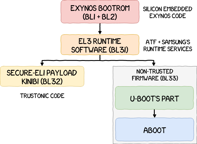
For devices running in the AArch64 processor state, ATF defines 5 sequential stages for the bootloader:
- Stage 1 (BL1): AP Trusted ROM;
- Stage 2 (BL2): Trusted Boot Firmware;
- Stage 3-1 (BL31): EL3 Runtime Software;
- Stage 3-2 (BL32): Secure-EL1 Payload (optional);
- Stage 3-3 (BL33): Non-trusted Firmware.
Some implementations might embed both BL1 and BL2 into the bootrom or might not need them at all. ATF handles this use case by allowing a board to reset directly to BL31.
SBOOT components are listed below and an illustration is also available in the next figure.
- BL1: the Exynos bootrom;
- BL31: the EL3 runtime software based on the open-source Arm Trusted Firmware (ATF);
- BL33: the Trusted Execution Environment OS (TEE-OS), the firmware running in Secure World;
- BL33: a bootloader based on U-boot for the NWd Android bootloader.
After Fernand’s article was released, the monitor’s implementation was replaced, starting from the Samsung Galaxy S8, by a high-entropy section, which suggests it was encrypted. It is unclear whether it was intended by Samsung in the first place or simply an after-the-fact reaction to prevent further research on the subject. To be able to read the monitor’s code, an EL3 exploit is necessary, or at least a routine capable of reading the physical memory arbitrarily.
In the section Trustonic’s Trusted OS Kinibi, a brief explanation was given on the implementation by Samsung of their own Runtime Services, which are registered using the structure given in the following snippet.
typedef struct rt_svc_desc {
    uint8_t start_oen;
    uint8_t end_oen;
    uint8_t call_type;
    const char *name;
    rt_svc_init_t init;
    rt_svc_handle_t handle;
} rt_svc_desc_t;
These structures provide a handler for custom SMCs. An SMC is referenced by an OEN, which stands for Owning Entity Numbers. The structure defines a range of OEN numbers that will be processed by this specific handler. It will be used later on, in the part dedicated to the exploitation in EL3 in an upcoming article, where a SMC handler will be modified to achieve code execution.
Conclusion
In this first part, we explained the different components of Samsung’s TrustZone based on Kinibi. While it is mainly theoretical, this article builds the foundations for the next parts of this series.
In the following article, we will present tools that were developed during this research and how they were used to reverse engineer and exploit TrustZone components more easily.
References
| [IDA_LOADER] | https://github.com/ghassani/mclf-ida-loader/ |
| [UNBOX] | https://medium.com/taszksec/unbox-your-phone-part-i-331bbf44c30c |
| [SBOOT] | https://blog.quarkslab.com/reverse-engineering-samsung-s6-sboot-part-i.html |
| [TEEGRIS] | https://allsoftwaresucks.blogspot.com/2019/05/reverse-engineering-samsung-exynos-9820.html |
Acknowledgement
Thanks to all of our colleagues who proofread this article!

