Security Analysis of Devices That Support SCPI and VISA Protocols

By Philippe Lin, Roel Reyes, Shin Li, and Gloria Chen (Trend Micro Research)
When a legacy protocol is connected via Ethernet, and subsequently to the internet, security issues arise. Standard Commands for Programmable Instruments (SCPI) is a legacy protocol that many advanced measurement instruments support. It can be issued via General Purpose Interface Bus (GPIB), Universal Asynchronous Receiver/Transmitter (UART), Universal Serial Bus (USB), or Ethernet. However, it is important to note that authentication is not innate in this protocol.
The SCPI protocol, now 30 years old, was initially designed for sensors communicating over serial lines. It was designed as a simple ASCII text protocol that makes adoption via different languages and hardware interfaces as easy as possible. (Even today, the SCPI consortium references SCPI as a standard that works well over RS-232 interfaces and with the BASIC programing language.)
Over time, many high-end sensor devices adopted the protocol, and of course, the Ethernet became the dominant hardware interface. Today, these devices are being exposed to the internet as more networks get connected, but they have never been designed for it and network administrators might not be aware that this is happening. It should also be noted that devices such as logic analyzers and room sensors do not run on known operating systems and do not show up on PC inventory lists.
Overview of the Research
Keysight Technologies of the Agilent Technologies is a key player in the market of measurement equipment. We have used its digital multimeters (DMM) and power supplies, but when we read their whitepaper describing how to use Python to automate the power supply for in-lab experiments, its Ethernet interface caught our attention.
We learned that SCPI, while not limited to Keysight, can be used in models where Ethernet is applicable; and port 5025, supported by Virtual Instrument Software Architecture (VISA), is open by default. The Python script in the whitepaper described how to reset the power supply, set voltage and current limit, measure the voltage and current, and switch the output channels on and off.
It can be dangerous to expose such a professional power supply to the internet, as it is usually connected to precise instruments in laboratories where a device under test (DUT) is usually very sensitive to input power. Overvoltage or overcurrent protection could be switched off, and the output can be hazardous to the DUT, causing electric shock, or even worse, a fire in the labs.
Since the protocol itself is designed without authentication/encryption, a fix is not available. We responsibly disclosed this research to the concerned vendors through Trend Micro’s Zero Day Initiative (ZDI).
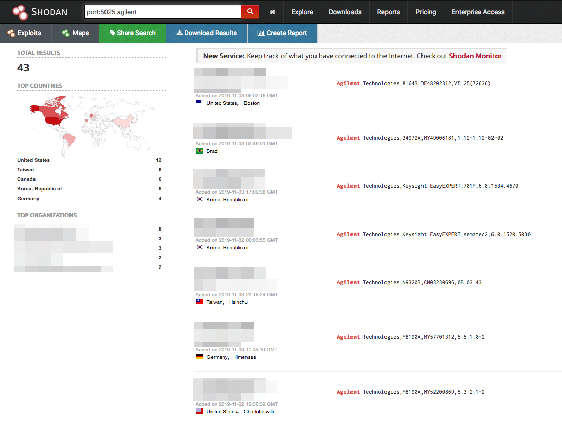
Figure 1. Some of the Keysight/Agilent devices exposed on Shodan
We did a quick Shodan scan and found several SCPI-compatible devices exposed on the internet. Fortunately, there were no such power supplies exposed on the internet. However, we did see expensive instruments; changing the parameter of which may also result in damaged units or chips.
| Modem | Quantity | Function |
| EasyEXPERT | 19 | GUI-based device characterization software |
| 34972A | 11 | Data acquisition system |
| M819xA | 9 | Arbitrary waveform generator |
| 3352xx | 4 | Function generators & synthesizers waveform gen |
| 344xxA | 2 | Digital multimeter |
| 81180A | 2 | Arbitrary waveform generator |
| 89601B | 2 | VSA software and X-Series signal analyzer |
| DSO6104x | 2 | 1 GHz oscilloscope |
| DSOS104A | 2 | 1 GHz oscilloscope |
| E836xC | 2 | PNA microwave network analyzer |
| 34980A | 1 | Multifunction switch/measure unit |
| 8164B | 1 | Lightwave measurement system |
| DSOS054A | 1 | 500 MHz oscilloscope |
| E4438C | 1 | ESG vector signal generator |
| E4446A | 1 | PSA high-performance spectrum analyzer |
| M8070B | 1 | M8000 BERTs and AWGs platforms control software |
| M9505A | 1 | 5-slot AXIe chassis |
| MSOS804A | 1 | High-definition oscilloscope |
| N9000B | 1 | CXA signal analyzer |
| N9320B | 1 | RF spectrum analyzer (BSA) |
| N9344C | 1 | Handheld spectrum analyzer (HSA) |
| N9923A | 1 | Portable battery-operated RF vector network analyzer |
Table 1. Exposed models and their functions
We had a Keysight 34461A Digital Multimeter in the office, so we looked into the potential issues that may arise when it is exposed on the internet.
Digital Multimeter (DMM): A Case Study
After consulting the operating and service guide, we noticed that all interfaces (even the web interface) were enabled by default and unprotected by passwords. Many parameters were also configurable. In addition to port 80, port 5024 (Telnet) and 5025 (SCPI) were likewise open to the public.
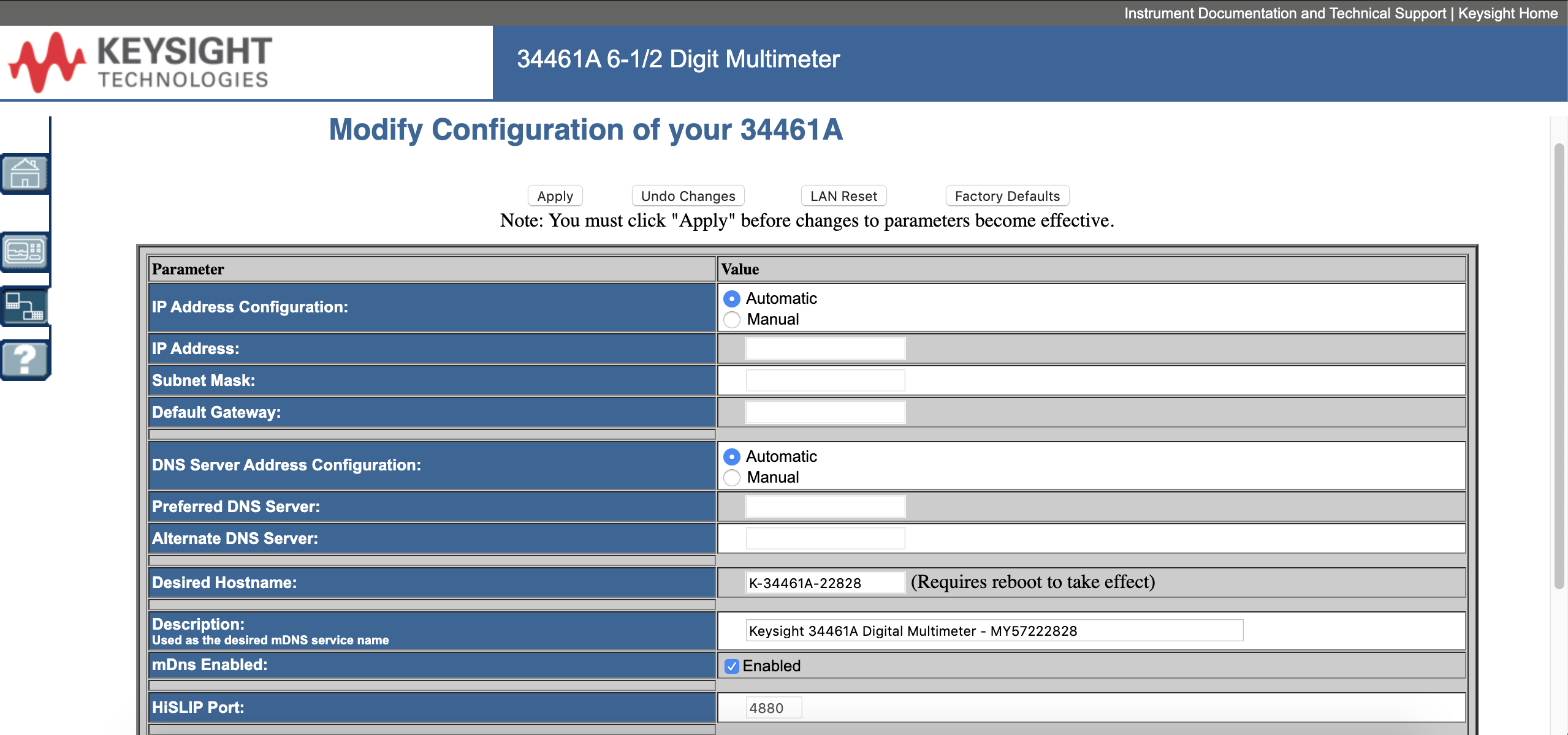
Figure 2. Web interface of Keysight 34461A Digital Multimeter
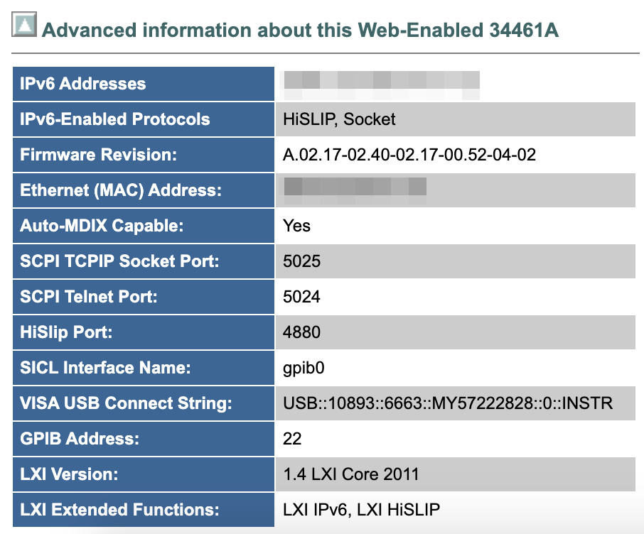
Figure 3. Network settings of Keysight 34461A Digital Multimeter
Once the password is set or changed, the owner has to do a hard reset or call the vendor to reset the multimeter. It is possible to issue common SCPI commands via port 5024 and 5025, so we tested PyVISA, the Python library that supports VISA, which works perfectly on port 5025. It runs on Telnet, as shown in the following example.
$ telnet 10.1.169.{BLOCKED} 5024
Trying 10.1.169.{BLOCKED}...
Connected to k-34461a-22828.client.tw.{BLOCKED}et.org.
Escape character is '^]'.
Welcome to Keysights's 34461A Digital Multimeter
34461A> *IDN?
Keysight Technologies,34461A,MY57222828,A.02.17-02.40-02.17-00.52-04-02
34461A> *ESR?
+32
34461A> *PSC?
1
34461A> SYST:ERR?
-113,"Undefined header"
We were able to read the measured voltage/current if there was a DUT connected to the multimeter.
34461A> MEAS:CURR?
+2.24079819E-09
34461A> MEAS:VOLT?
-5.23101894E-05
It should be noted that while it is possible to leak the measurement data of the DUT, a digital multimeter is not a power supply and cannot cause too much harm if the measured data points are not the source of any actuator. If they are, any change to CALCulate:SCALe:GAIN or CALCulate:SCALe:OFFSet would cause problem in the downstream.
To cause damage to the instrument itself, one could set PSC to 0 and issue tens of thousands of *ESE commands, which may cause a write cycle to non-volatile memory at each command. The non-volatile memory can be written for a limited number of times, but excessive write could result in physical corruption, where a broken instrument can be only fixed by replacing the part.
If the instrument is a power supply, it is possible to remove output protection by issuing OUTP:PROT:CLE. Once removed, one could set the voltage and current to the maximum value a device is capable of outputting. Moreover, *TRG or GPIB bus triggers followed by an *OPC? command cause a denial of service (DoS), which can only be fixed by a GPIB DCL (device clear) command.
One trick a threat actor can use on most — if not all — exposed devices, is the DISP:TEXT command, which shows text on the front panel. It causes no harm, but it might be off-putting to see a different screen display.
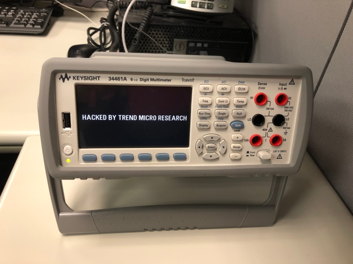
Figure 4. DISP:TEXT sample on front panel
A threat actor could also set up a secure code (calibration password) to prevent the real owner from changing important configurations. It could cause some chaos, but the owner could make adjustments to prevent accidental or unauthorized modifications to the instrument.
Automated Test Fields: An Attack Scenario
Even though a power supply unit (PSU) is not found exposed on the internet, the readings of an exposed DMM could be changed by other parties (regardless of intent), resulting in a cascading effect. We have consulted a handbook for test engineers for an imaginary scenario of an automated test.
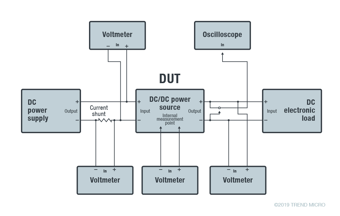
Figure 5. Block diagram of a test system used for research and development (R&D), based on a figure from a handbook document by Agilent Technologies
The PSU on the left (as seen on Figure 5) provides a predefined voltage and current to the DUT. However, the voltage in the circuit is measured at multiple points to ensure that it supplies the correct power, especially on the secondary side of a transformer circuit. The readings on the PSU is not fully reliable, and is adjusted accordingly (that is, manually controlled) or adjusted via a feedback loop (semi-controlled or automated).
In an automated, controlled environment, manipulated readings in multiple points would cause a false feedback that raises or lowers the voltage proveided by the PSU, thus damaging the DUT.
In a production system, the DMM, function generators, oscilloscope, and DUT are all connected to an LXI or SCPI bus over RS485 or Ethernet. The test sequence is, to be concise and abstract, similar to the description in the following table.
| Program step | Input condition (stimulus to DUT) | Measurement setup (to measure signal out of DUT) | DUT measurements taken |
| 1 | Set input condition 1 (0 degrees C) | ||
| 2 | Prepare measurement setup 1 (voltage) | ||
| 3 | Test point 1 voltage | ||
| 4 | Test point 2 voltage | ||
| 5 | Test point 3 voltage | ||
| 6 | Set input condition 2 (25 degrees C) | ||
| 7 | Test point 1 voltage | ||
| 8 | Test point 2 voltage | ||
| 9 | Test point 3 voltage | ||
| 10 | Set input condition 3 (55 degrees C) | ||
| 11 | Prepare measurement setup 2 (current) | ||
| 12 | Test point 1 current | ||
| 13 | Test point 2 current | ||
| 14 | Test point 3 current |
Table 2. An excerpt of a test sequence sample in an automated test, based on a table from a handbook document by Agilent Technologies
When a stimulus changes (i.e., a change in temperature, like in the table), the test system has to wait for a stabilized DUT before measurements can be taken. Timing sensitive components have to be measured (e.g., phase lock loop [PLL] and the stabilization of a low-dropout [LDO] regulator). If a measurement is manipulated, the PLL clock phase might be confounded or the DUT might be burned by inrush current.
Conclusion and Security Recommendations
SCPI commands are very useful in many implementations and can even change almost any setting on instruments that support the protocol. Although we have taken the Keysight digital multimeter as an example for this blog, the SCPI protocol is, in fact, supported by major instrument vendors. It’s possible that the impact may not only be limited in laboratories with expensive DUTs, but also semiconductor automated test equipment (ATE). Securing measurement instruments can be done by following our recommended practices such as:
- Never expose the instruments to the internet
- Put the instruments in an isolated network or a separated virtual LAN (VLAN) if an Ethernet connection is a must
- Set a security code (calibration password) to prevent unauthorized deletion of licenses and calibration
- Implement a safety circuit in case the power supply is connected to a high-precision DUT (in case the output has been tampered on the internet/intranet)
- Consider the possibility that the reading can be tampered with on the internet/intranet if the multimeter readings are fed to an actuator
- Deploy inbound and outbound traffic monitoring (i.e., for suspicious behavior or abnormal access to laboratory devices) through network intrusion tools like Trend Micro
 Deep Discovery Inspector
 and TippingPoint
The post Security Analysis of Devices That Support SCPI and VISA Protocols appeared first on .

 Deep Discovery Inspector
